
Mechanics of Materials: Stress Transformation
Stress Transformation
Often times, like in the case of the pressure vessels that we studied in the previous lesson, the stress in one direction is really small compared with the other two. When this is the case, it is convenient to neglect the small stress, and instead of evaluating the stress acting on a cubic element within the material, we can examine the stress acting on a plane.
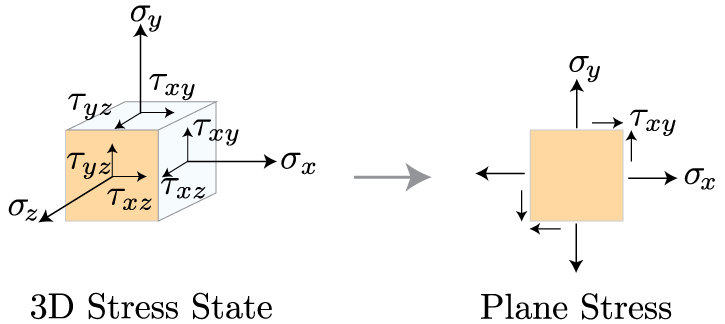
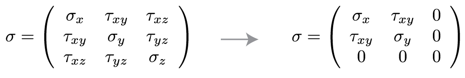
These two states of stress, the 3D stress and plane stress, are often discussed in a matrix, or tensor, form. As we reduce the dimensionality of the tensor from 3D to 2D, we get rid of all the terms that contain a component in the z direction, such that
Now that we've reduced our state of stress to two dimensions, we can learn how to transform the coordinates along which these stress components act into any coordinate frame we are interested in. Why would we want to do that? Well, take a look at the image below. >
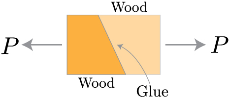
Two pieces of wood, cut at an angle, and glued together. The wood is being pulled apart by a tensile force P. How do we know if the glued joint can sustain the resultant stress that this force produces? We need to calculate the normal and shear stresses perpendicular and parallel to the joint. Therefore, we need to rotate, or transform, the coordinates associated with the force P to the direction associated with the angle of the glued joint. Then, we can evaluate the stresses along these new directions, x' and y'.
Once we've rotated the coordinate system, we need to transform the forces acting in the old coordinate frame to this new coordinate frame. That means, we must draw a detailed free body diagram. If we take the a differential element near the origin of the new coordinate system, we can get the forces acting on each surface from the stress times the differential area.

As you'll notice from the free body diagram, most of the forces aren't pointing in the directions we're interested in, that is x' and y'. So, we need to break these forces into their components, and sum the resulting forces in the directions of our new coordinate system. This results in a long, but straightforward, calculation given below.

We can stop here if we'd like. However, if we make use of a couple trigonometric identities, we can make these equations a bit more friendly looking.

Using these identities, we can get rid of all those squared sines and cosines. The final result for the normal and shear stresses in our new coordinate system (denoted by theta, which is a counterclockwise rotation from the x axis to the x' axis) is given by
Principal Stress & Mohr's Circle
We have just shown that the magnitude of the normal and shear stress will depend on the coordinate system you choose. If you rotate the coordinate system by some angle, the magnitude of these stresses will change. As you may suspect, certain angles will correspond to maximum and minimum values of these stresses. One way to determine the extrema of a function is to differentiate it with respect to the variable of interest, and set the resulting equation equal to zero.

Now, we can solve for theta by recalling the relationship between sines, cosines, and tangents, such that
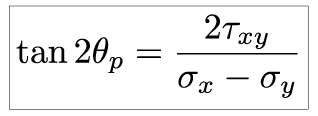
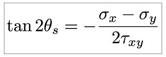
We've included a subscript p on theta to identify this angle as the plane corresponding to the maximum and minimum normal stresses. This equations has two roots, i.e. two values of theta will satisfy it. These two values will be separated by 90o (or, 2*theta will be separated by 180o). One angle will correspond to the maximum normal stress, and the other will correspond to the minimum. We will talk about identifying which is which shortly. First, let's point out that we can repeat this same procedure to determine the angle at which the element will be subjected to maximum and minimum shear:
Now that we have the planes on which stress will be at a maximum and minimum, we need to identify the magnitude of these principal stresses. There are various ways to accomplish this, but the general idea should look familiar to anyone who has seen linear algebra techniques. We aim to diagonalize our plane stress tensor, and the resulting eigenvalues will correspond to the extrema of our stress state.

Our goal for finding the principal stresses on an element is to eliminate the dependence of the stress transformation equations on theta. The equations describing stress transformation are the parametric equations of a circle. We can eliminate theta by squaring both sides and adding them (I have taken the liberty to transpose the first term on the right hand side of the equation, which is independent of theta, and corresponds to the average stress).

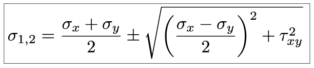
That calculation looks far worse that it is. Again, we simply transposed the average stress, squared both sides, and added the equation for the normal stress to the equation for the shear stress. Things simply quite nicely. The second term on the right hand side of each equation cancels out. What we're left with are sine square plus cosine squared terms, and we recall from our trigonometric identities that this term equals zero. The resulting equation contains the principal normal and shear stresses. The principal normal stress will occur when the shear stress is zero, which means
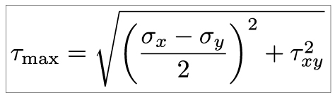
The principal shear stress is simply the square root term
An alternative to using these equations for the principal stresses is to use a graphical method known as Mohr's Circle. This involves creating a graph with sigma as your abscissa and tau as your ordinate, and plotting the the given stress state. The sign convention is as follows
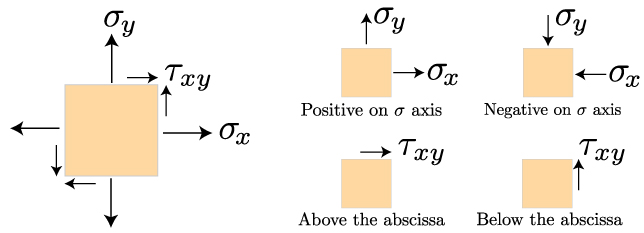
We will plot two points. The normal and shear stress acting on the right face of the plane make up one point, and the normal and shear stress on the top face of the plane make up the second point. These two points lie on a circle. The center of that circle is the average normal stress. The radius of that circle is the maximum shear stress. The largest value of of sigma is the first principal stress, and the smallest value of sigma is the second principal stress.
Summary
In this lesson, we learned how to transform a state of plane stress into a new reference, or coordinate, frame. This process is important when it is necessary to consider how an external force induces stress along a given plane within the material. This plane may be the natural angle of a wood's grain, the angle of a welded or glued joint, or the angle of a notch within a structure. This process showed us that the stress within a material will vary depending on which angle you consider, which means there will be an angle at which the stress will be at a maximum or minimum. We calculated these angles, and the magnitude of the principal stresses within the material. This is important for determining the maximum stress a structure is exerted to when experiencing a complex loading. These principal stresses will be the design criteria used to prevent material failure.
 This material is based upon work supported by the National Science Foundation under Grant No. 1454153. Any opinions, findings, and conclusions or recommendations expressed in this material are those of the author(s) and do not necessarily reflect the views of the National Science Foundation.