
Mechanics of Materials: Torsion
Torsional Deformation
Torque is a moment that twists a structure. Unlike axial loads which produce a uniform, or average, stress over the cross section of the object, a torque creates a distribution of stress over the cross section. To keep things simple, we're going to focus on structures with a circular cross section, often called rods or shafts. When a torque is applied to the structure, it will twist along the long axis of the rod, and its cross section remains circular.
To visualize what I'm talking about, imagine that the cross section of the rod is a clock with just an hour hand. When no torque is applied, the hour hand sits at 12 o'clock. As a torque is applied to the rod, it will twist, and the hour hand will rotate clockwise to a new position (say, 2 o'clock). The angle between 2 o'clock and 12 o'clock is referred to as the angle of twist, and is commonly denoted by the Greek symbol phi. This angle lets us determine the shear strain at any point along the cross section.

Before we get into the details of this equation, it's important to note that because we're only discussing circular cross sections, we've switched from Cartesian coordinates to cylindrical coordinates. That's where the Greek symbol rho came from – it denotes the distance along the cross section, with rho=0 at the center and rho=c at the outer edge of the rod.
We can immediately learn a few things from this equation. The first thing might be obvious: the more angle of twist, the larger the shear strain (denoted by the Greek symbol gamma, as before). Second, and this is the big difference between axial-loaded structures and torque-loaded ones, the shear strain is not uniform along the cross section. It is zero at the center of the twisted rod, and is at a maximum value at the edge of the rod. Finally, the longer the rod, the smaller the shear strain.
So far, we've focused our attention on displacements and strain. To discuss the stress within a twisted rod we need to know how torque and stress relate. Since twist applies a shear strain, we expect that torque will apply a shear stress. The relationship between torque and shear stress is detailed in section 5.2 of your textbook, and it results in the following relation:
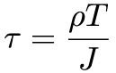
In this equation, J denotes the second polar moment of area of the cross section. This is sometimes referred to as the "second moment of inertia", but since that already has a well-established meaning regarding the dynamic motion of objects, let's not confuse things here. We'll discuss moment's of area in more detail at a later point, but they take on a very simple form for circular cross sections:
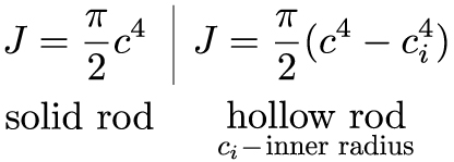
(Note: those are both the same equation – solid rods have an inner radius of ci=0).
Now we have equations for our shear strain and our shear stress, all that is left to do is use Hooke's law in shear to see how they are related. Hooke's law lets us write down a nice equation for the angle of twist – a very convenient thing to measure in lab or our in the field.

And, just like we saw for axial displacements, we can use superposition for our shear deformations as well:

This final equation allows us to split up torques applied to different parts of the same structure. Let's work out a problem, and see if we understand what's going on for torsional deformations.
Power Transmission
One of the most common examples of torsion in engineering design is the power generated by transmission shafts. We can quickly understand how twist generates power just by doing a simple dimensional analysis. Power is measured in the unit of Watts [W], and 1 W = 1 N m s-1. At the outset of this section, we noted that torque was a twisting couple, which means that it has units of force times distance, or [N m]. So, by inspection, to generate power with a torque, we need something that occurs with a given frequency f, since frequency has the units of Hertz [Hz] or [s-1]. So, the power per rotation (2*pi) of a circular rod is equal to the applied torque times the frequency of rotation, or:

On the far right hand side of the equation, we've used the relation that angular velocity, denoted by the Greek letter omega, is equal to 2pi times the frequency.
Statically Indeterminate Problems
One equation, two unknowns… we've been down this road before need something else. Although the type of loading and deformation are different, the statically indeterminate problems involving the torsion of rods are approached in the exact same manner as with axially loaded structures. We start with a free body diagram of twisted rod. Take, for example, the rod in the figure below, stuck between two walls.
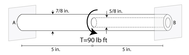
Immediately upon inspection you should note that the rod is stuck to two walls, when only one would be necessary for static equilibrium. More supports than is necessary: statically indeterminate. And statically indeterminate means, draw a free body diagram, sum the forces in the x-direction, and you'll get one equations with two unknown reaction forces. So, we need to consider our deformations – for torsion, that means let's turn to our equation that describes the superposition of twist angles. For this equation, we should note that half the rod is solid, the other half is hollow, which affects how we calculate J for each half. Most importantly, we need to ask ourselves "what do we know about the deformation?" Well, since the rod is stuck to the wall at edge, the twist at A and B must be equal to zero (just like the displacement in the last section). See if you can work the rest of this problem out on your own: What is the torque in each half of the rod?
(Answer: Ta=51.7 lb ft & Tb=38.3 lb ft).
Summary
We learned about torque and torsion in this lesson. This different type of loading creates an uneven stress distribution over the cross section of the rod – ranging from zero at the center to its largest value at the edge. From this analysis we can develop relations between the angle of twist at any a point along the rod and the shear strain within the entire rod. Using Hooke's law, we can relate this strain to the stress within the rod. We also used a method of dimensional analysis to determine the power generated by a transmission shaft (i.e. a rod) that spins with a given frequency under an applied torque. Finally, we showed that torsion problems are also often statically indeterminate, and even though the loading and deformation is different, the technique we established in the last section for solving problems with axial loading is the same technique for solving problems with torque loading.
 This material is based upon work supported by the National Science Foundation under Grant No. 1454153. Any opinions, findings, and conclusions or recommendations expressed in this material are those of the author(s) and do not necessarily reflect the views of the National Science Foundation.